PB-series RS485-1 and CAN: a documented reference
The January 2024 PB-series document, PDF page 13, numbers the two sockets together: RS485-1 is 1-8 and CAN is 9-16. The table preserves that numbering. Read the socket-view drawing in the source; do not count pins from a reversed plug view.
This is a reference for the assembly pictured in that document, not a universal cable recipe or a confirmed V19 pinout. If your model, revision or connector layout differs, stop and request the matching drawing before wiring. Do not infer unused pins are safe on another board.
| Socket in source | Drawing pins | Signal in source |
|---|---|---|
| RS485-1 | 1, 8 | RS485-B1 |
| RS485-1 | 2, 7 | RS485-A1 |
| RS485-1 | 3, 6 | GND |
| RS485-1 | 4, 5 | NC |
| CAN (numbered 9-16) | 12 / 13 / 15 | CANL / CANH / GND |
| CAN (numbered 9-16) | 9, 10, 11, 14, 16 | NC |
Related products and current prices
Examples from the current catalog, not a compatibility shortlist. Confirm the exact BMS, firmware, pinout and included package before ordering. Prices in USD.
All JKBMS models and accessories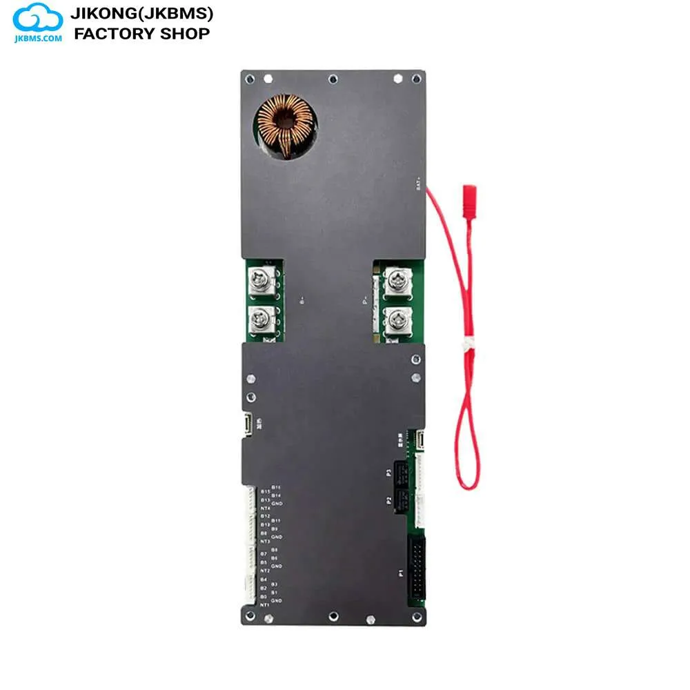
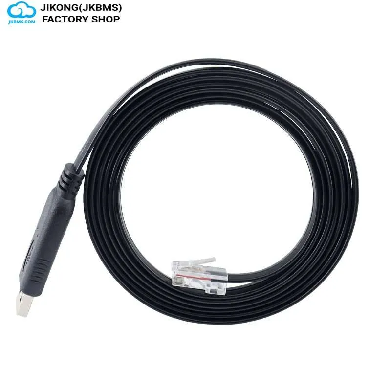
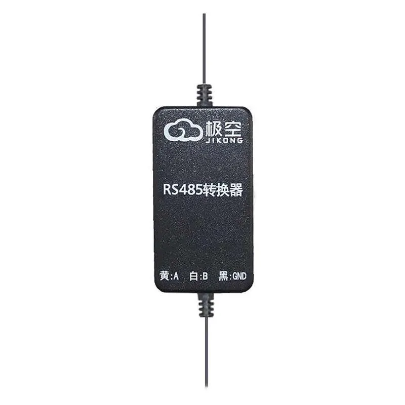
An RJ45 socket does not imply Ethernet
The 8P8C socket used for RS485 and CAN on battery equipment is the same connector used for Ethernet, but it carries a completely different signal set. Connecting a BMS communication port to a network switch, router, or PoE port can damage the port or the board.
Treat every RJ45 socket on a BMS as a proprietary serial or CAN interface until the manual for that model states otherwise.
Verify the pin assignment against your model manual
Pin assignment varies between model families and between hardware revisions within a family. Do not copy a pinout from a forum post, a different model, or the inverter end of a cable.
The authoritative source is the manual for your exact model and hardware version. Confirm which pins carry RS485 A and B, which carry CAN High and Low, and critically, whether any pin carries a supply voltage. A supply pin landing on a data pin is the usual cause of a dead port.
- Identify the exact model and hardware revision printed on the board
- Open the manual for that model rather than a similar one
- Note which pins are data, which are ground, and which carry supply
- Check continuity of a prebuilt cable before energising it
RS485 and CAN are not interchangeable
RS485 is a differential serial bus that carries whatever protocol the two ends agree on, commonly a Modbus-style request and response. CAN is a message-based bus with its own frame format and arbitration. The electrical layers differ and the protocol layers differ.
An inverter that expects CAN will not communicate with a BMS port configured for RS485 even when the cable fits. Confirm which bus the inverter requires, then confirm the BMS supports that bus on that port.
Termination, grounding and cable runs
Both RS485 and CAN are intended to run as a linear bus with termination at the two physical ends. Star topologies, long stubs, and missing or doubled termination produce intermittent faults that look like a failing BMS.
Use twisted pair for the differential signals, keep the communication run away from battery power cabling, and establish a single reference ground rather than relying on the enclosure.
- Run the bus as a chain, not a star
- Terminate only the two physical ends of the bus
- Keep data cable separated from high-current DC runs
- Avoid extending a run by joining unshielded patch cables
Match the protocol before blaming the wiring
Once the cable is correct, remaining faults are usually protocol selection: baud rate, the inverter brand profile selected on the BMS, and the battery address or protocol number set on the inverter must all agree.
Change one setting at a time and confirm against both the BMS manual and the inverter manual. Record the working combination for the next installation.
Questions this raises most often
No. Pin assignment varies between model families and hardware revisions, so the pinout must be confirmed in the manual for your exact model and hardware version before wiring.
No. The RJ45 socket carries RS485 or CAN signals, not Ethernet. Connecting it to a network switch or PoE port can damage the port or the board.
The connector is shared across the industry but the pin assignment and the bus type are not. Confirm whether the inverter expects RS485 or CAN, then confirm the pinout and the selected protocol profile on both ends.
Terminate only at the two physical ends of the bus. Additional termination in the middle, or termination on a stub, causes intermittent communication faults.
Take it to a part number
Ratings vary between codes that read almost the same, so settle the decision here and then confirm the figures on the product page for the exact code.